
Anchors & Ports
Eclipse Sprotty provides different Routing algorithm to connect nodes with a edge.
The start and the end point of an edge is connected to your node element. The connection point can be controlled by either an Anchor Computer or by defining Ports. Both concepts will be introduced in the following sections.
AnchorComputers
Each Router algorithm provided by Sprotty defines so called IAnchorComputers which are responsible to compute the exact position the start and end of a edge is connected with the connected node element. Sprotty already defines different Default AnchorComputers, so if you do not define a custom implementation the edge will end at the boundaries of the node element.
You can implement your own AnchorComputer to compute the exact position an edge should target you Node Elements.
The Interface IAnchorComputer
For a custom implementation you need to implement the Interface IAnchorComputer:
import { injectable } from 'inversify';
import {
	Bounds,
	Point,
	ManhattanEdgeRouter,
	SConnectableElement,
	IAnchorComputer
} from 'sprotty';

export const CUSTOM_TASK_ANCHOR_KIND = 'custom-task';

/**
 * This CustomTaskAnchor computes a custom anchor point for a task element.
 */
@injectable()
export class CustomTaskAnchor implements IAnchorComputer {

	static KIND = ManhattanEdgeRouter.KIND + ':' + CUSTOM_TASK_ANCHOR_KIND;

	get kind(): string {
		return CustomTaskAnchor.KIND;
	}

	getAnchor(connectable: SConnectableElement, refPoint: Point, offset: number): Point {
		// compute an custom anchor point
       .....
		return { x: customXPos, y: customYPos };
	}
}
You need to provide a unique AnchorKind so that the Router algorithm can choose the correct AnchorComputer.
In the Method getAnchor you can now compute the x/y position within your element which is provided in the parameter connectable. The parameter refPoint defines the position from where the edge is entering you element and the offset defines an optional offset.
Next you need to overwrite the method get anchorKind() in you SNode implementation to give the router algorithm a hint which AnchorComputer to choose. It is possible to implement different AnchorComputers for different router algorithim. In the example above we define a CustomTaskAnchor for the ManhattanEdgeRouter with the name ‘custom-task’. This name need to be returned by the CustomTaksNode implementation within your model:
export class CustomTaskNode extends RectangularNode {
     ....

    /*
     * Returns the anchorComputer Kind for CustomTaskNode
     */
     get anchorKind(): string {
        return CUSTOM_TASK_ANCHOR_KIND;
    }
}
Finally you need to bind your CustomAnchor in your ContainerModule:
const myDiagramModule = new ContainerModule((bind, unbind, isBound, rebind) => {
    ....

    // bind the Custom AnchorComputer
    bind(TYPES.IAnchorComputer).to(CustomTaskAnchor).inSingletonScope();
    ....
}
  .....
That's it. Now each time you connect an edge with your CustomTask the CustomTaskAnchor computer will be choosen to compute the exact position to connect the edge with your node element.
Ports
Another way to define how edges are connected with our node elements are Ports. Ports describe specific docking points for a graphical node element to connect edges. If you do not define explicit ports, the endpoint is computed by a AnchorComputers at the outer bounderies of your element.
If you define ports, edges can only be placed on the specific docking positions within your node element. This gives you more control about the design and layout of your diagrams. And the port will also become part of your model.
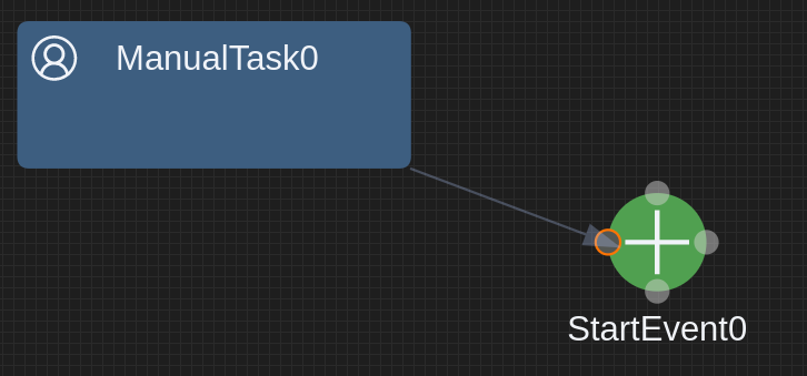
The following example shows a more complex graphical representation. The Element consists of symbol (circle) and label below:
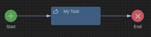
So the outer bounders of the complete element are not useful to compute the edge endpoint as it will be done by the default AnchorComputer. We want to connect the edges only to the symbol above the label. For this we can define a Port.
The GLSP Server
On the server part we first define a new model type for our custom type:
public final class ModelTypes {
    private ModelTypes() { }
    ....

    public static final String EVENT_PORT = "event:port";
    ...
}
In your NodeBuilder implementation you can now add a new property to your model element defining this port type:
public class EventNodeBuilder extends AbstractGNodeBuilder<EventNode, EventNodeBuilder> {

    .....

    public void setProperties(final EventNode node) {
        super.setProperties(node);
        ...
        node.getChildren().add(createPort(node, -20.0, -20.0, "_port"));
    }

    public static GPort createPort(final BaseElement node, final Double x, final Double y, final String subId) {
        return new GPortBuilder(ModelTypes.EVENT_PORT) //
                .id(node.getId() + subId) //
                .position(x, y) //
                .size(40.0, 40.0) //
                .addCssClass("event-port").build();
    }
}
And in your DiagramConfigurationClass you need to map the new port type to the GLSP standard GPPORT implementation and add your new Port as a target/source for the edgeTypeHints:
public class BPMNDiagramConfiguration extends BaseDiagramConfiguration {

	.....

    @Override
    public Map<String, EClass> getTypeMappings() {
    	.....
    	mappings.put(ModelTypes.EVENT_PORT, GraphPackage.Literals.GPORT);
    	....
    }
    @Override
    public List<EdgeTypeHint> getEdgeTypeHints() {
        List<EdgeTypeHint> edgeHints = new ArrayList<>();

        // SequenceFLow
        EdgeTypeHint myEdgeHint = createDefaultEdgeTypeHint(ModelTypes.SEQUENCE_FLOW);

        myEdgeHint.setSourceElementTypeIds(Arrays.asList(//
                ModelTypes.MANUAL_TASK, //
                ModelTypes.EVENT_PORT));

        myEdgeHint.setTargetElementTypeIds(Arrays.asList(//
                ModelTypes.MANUAL_TASK, //
                ModelTypes.EVENT_PORT));

        edgeHints.add(sequenceFlowHint);
        return edgeHints;
    }
}
The GLSP Client
Now your server model provides additional port information to the client. To render the ports on your client, you have to provide the port element within your diagram configuration:
const myDiagramModule = new ContainerModule((bind, unbind, isBound, rebind) => {

    .....
    configureModelElement(context, 'event:port', SPort, CircularNodeView, { disable: [selectFeature] });
    ......
});
In this example we define a CicularNodeView to represent our port which has the same dimensions and position as the Circle Symbol.
When you configure the new port ModelElement the optional argument parameter must include the definition { disable: [selectFeature] } .
This is needed because the GPLSP ChangeBoundsTool (i.e. user driven resize or move) is tightly coupled with the element selection.
The selection tool always tries to select the topmost element at the current mouse position. If this element is not selectable it navigates up the parent hierarchy and looks for selectable elements there.
As a port is selectable by default and rendered on top of our symbol when you point to the symbol area with the mouse, you actually select the port and not the symbol which will block the node element to be moveable because a port itself is not movable. For that reason we disable the selectFeature for the port during configuration:
configureModelElement(context, 'myPort', SPort, RoundedCornerNodeView, { disable: [selectFeature] });
In case you have defined custom views you need to ensure that your ports are rendered by calling the renderChildren method.
@injectable()
export class EventNodeView extends ShapeView {
	render(element: EventNode, context: RenderingContext): VNode | undefined {
		if (!this.isVisible(element, context)) {
			return undefined;
		}
	....
			vnode = (
				<g transform={'scale(1) translate(0,0)'} class-sprotty-node={true}>
					<circle r="20" cx="0" cy="0" ></circle>
					<g class-icon={true}>
						<path transform={'scale(2.0) translate(-7.5,-7.5)'}
							d={eventSymbol} />
					</g>
					{context.renderChildren(element)}
				</g>
			);
	....
}
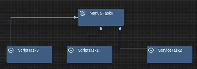
Defining multiple Ports
In the example above I have defined one single Port for my graphical node element. But in some cases you whant to define multiple ports on different positions:
The GLSP Server
First of all you have to define ports along with your node builder class
public class CustomTaskNodeBuilder extends AbstractGNodeBuilder<TaskNode, TaskNodeBuilder> {

	....

   @Override
   public void setProperties(final TaskNode node) {
      super.setProperties(node);
      .....
      node.getChildren().add(createPort(node, -5.0, -25.0, "_north"));
      node.getChildren().add(createPort(node, -25.0, -5.0, "_west"));
      node.getChildren().add(createPort(node, 15.0, -5.0, "_east"));
      node.getChildren().add(createPort(node, -5.0, 15.0, "_south"));
   }

   private GPort createPort(final TaskNode node, final Double x, final Double y, final String subID) {
      return new GPortBuilder()
         .id(node.getId() + subID)
         .position(x, y)
         .size(5.0, 5.0)
         .build();
   }
}
Next you need to extend your DiagramConfiguration by providing the EdgeHints:
public class MyDiagramConfiguration extends BaseDiagramConfiguration {

   ....
DefaultTypes.PORT
   /**
    * Returns the edge type hints for the diagram implementation. Edge type hints are sent to the client and used to
    * validate whether certain operations for edges are allowed without having to query the server again.
    *
    * @return List of all edge type hints for the diagram implementation.
    */
   @Override
   public List<EdgeTypeHint> getEdgeTypeHints() {
      List<EdgeTypeHint> edgeHints = new ArrayList<>();
      edgeHints.add(createDefaultEdgeTypeHint(EDGE));
      EdgeTypeHint sequenceFlowHint = createDefaultEdgeTypeHint(ModelTypes.SEQUENCE_FLOW);
      edgeHints.add(sequenceFlowHint);
      return edgeHints;
   }

   @Override
   public EdgeTypeHint createDefaultEdgeTypeHint(final String elementId) {
      EdgeTypeHint hint = super.createDefaultEdgeTypeHint(elementId);
      // allow tasks and ports
      hint.setSourceElementTypeIds(Arrays.asList(DefaultTypes.PORT,ModelTypes.MANUAL_TASK));
      hint.setTargetElementTypeIds(Arrays.asList(DefaultTypes.PORT,ModelTypes.MANUAL_TASK));
      return hint;
   }
	....

}
The GLSP Client
Now your server model provides additional port information to the client. To render the ports on your client, you have to provide the port element within your diagram configuration:
const myDiagramModule = new ContainerModule((bind, unbind, isBound, rebind) => {

    .....
    configureModelElement(context, 'myPort', SPort, RoundedCornerNodeView, { disable: [selectFeature] });
    ......
});
In case you have defined custom views you need to ensure that your ports are rendered by calling the renderChildren method.
@injectable()
export class EventNodeView extends ShapeView {
	render(element: EventNode, context: RenderingContext): VNode | undefined {
		if (!this.isVisible(element, context)) {
			return undefined;
		}
	....
			vnode = (
				<g transform={'scale(1) translate(0,0)'} class-sprotty-node={true}>
					<circle r="20" cx="0" cy="0" ></circle>
					<g class-icon={true}>
						<path transform={'scale(2.0) translate(-7.5,-7.5)'}
							d={eventSymbol} />
					</g>
					{context.renderChildren(element)}
				</g>
			);
	....
}
Layout
The ports can be designed in various ways by just providing CSS definitions. See the following example which highlights the ports only if a edge modification is recognized:
.sprotty-node .sprotty-port {
	stroke-width: 1;
	stroke: transparent;
	fill: transparent;
}
.sprotty-graph.edge-modification-not-allowed-mode .sprotty-node:hover .sprotty-port,
.sprotty-graph.edge-creation-select-target-mode .sprotty-node:hover .sprotty-port,
.sprotty-graph.edge-reconnect-select-target-mode .sprotty-node:hover .sprotty-port {
	fill: #d4d4d478;
}
.sprotty-graph.edge-creation-select-target-mode .sprotty-node .sprotty-port.mouseover,
.sprotty-graph.edge-reconnect-select-target-mode .sprotty-node .sprotty-port.mouseover {
	fill: rgb(85, 87, 83);
	stroke: #f57900;
}